Wednesday, June 9, 2010

Homemade Beck Magnetic Pulser


Magnetic Pulsing


I've been looking more into the Beck Protocol since learning to make colloidal/ionic silver. I will be talking more about these technologies in the near future. It is important for a few reasons. First, I believe in independence. I don't want to rely on big pharma to get drugs that will probably do more damage than good anyway. Secondly, an economic downturn is happening and this technology makes treating yourself and loved ones very easy and economical. Thirdly, I just don't trust big pharma.

Today I will be talking about the magnetic pulser. In theory it is used for treatment of pain and also to kill off pathogens that are in lymph nodes and not in the blood. In other words, this is to be in conjunction with blood electrification. In fact, the pulser causes causes blood electrification during the 2.5 ms pulse. Actually, you get four jolts of microamps in the tissue for each pulse.

As the first pulse is rising, current flows. Then on the downsize back to zero volts at the coil causes a reverse current in the tissue. Then the back emf from the collapsing field generates a current in the tissue but at the opposite polarity as the initial pulse. Then a reverse of that when that field subsides. It happens each time the magnetic field changes or moves.

The trick with the strobe light is to turn it to the lowest setting that it will still pulse at. This takes longer between each pulse, but they are waaaayyyy stronger. So, do that for deep penetration. For more shallow treatments, use a higher or faster setting.


All you do is find a strobe or a camera flash. Take it apart and use a resistor to short out the capacitor.

BE CAREFUL WITH THIS CAPACITOR. IT CAN HAVE 300 VOLTS STORED AND CAN STOP YOUR HEART. If you are unsure, ask someone qualified in electronics such as a TV repairman or an electrician to help.

Once you discharge the capacitor, then you can cut the line to one side of the strobe light and connect the two wires going to the coil.
To make the coil, get some coated copper wire, called magnet wire. Try to use 15 or 16 gauge. I used 15. Make a jig like in the picture below and hand wind or you can stick a bolt through it and use a hand drill. I used electrical tape on it before I took the one wood plate off to remove the coil. You need to secure it somehow, because it will try to unwind slightly.


Also, when running, the flash tube gets hot after about 15 minutes. Take a break and let it cool down. As it gets hot, it offers more resistance to the coil. I put electrical tape on the front to block some of the light. But I kept the cooling vents on the top and bottom alone.

I also added two capacitors in parallel to the existing capacitor. Just make sure positive to positive and negative to negative and that the voltage rating is good. I used capacitors from two more camera flashes, so the voltage rating was about 300 volts. I have 450 MicroFarads now instead of just the 8 MFDs that are standard with this strobe light.

Richard

Thursday, April 22, 2010

DIY Solar Intensity Meter - Pyranometer

A pyranometer or solar irradiance meter is used for measuring sunlight intensity at a given location. It reads in watts per square meter or W/m^2. This DIY project isn't technically a pyranometer because it doesn't use heat in any way to measure light intensity. Instead, it uses a solar panel. This could be any small solar panel, like the ones in old calculators. Normally, a pyranometer and even a lux meter will do a cosine correction. What this means is that the meter collects light coming from all angles and measures it. It usually does this with a hemisphere shaped diffuser. But if you are testing for solar intensity for solar applications, then you don't need it. In fact, it is more useful without the cosine correction.

For instance, if a solar panel is perpendicular to the sun, then that is its max power. It's angle would be zero degrees and the cosine of zero is 1. If you turn it to 90 degrees off axis to the sun then you would get no power because the cosine of 90 is 0. (Well, you actually get some power because of reflected light hitting the solar panel)

Let's say you are testing a spot for solar and you use one of the expensive pyranometers. You place it on your roof and get 800 watts per square meter. Then you use the homemade version using a small solar cell. It shows 800 w/m^2 as well, but only if you hold it perpendicular to the sun. If you lay it flat on the roof like you plan on mounting the solar panels it shows only 480 w/m^2. So, in a way the homemade is better because it shows you which angle is the best for the most power.

You can't just measure voltage because it isn't linear on a solar cell. You have to apply a set resistance and then as the light goes up, the current goes up and the voltage goes up, but linear in this case because of the set resistance.

I start off by using an old volume control (potentiometer) and hook it up between the two solar cell wires. I then set my meter to milivolts. I want 1 milivolt to equal1 watt per square meter.

I then find a site that shows local weather statistics. I found this one that shows the data from a school very close to me. http://www.victoriaweather.ca/station.php?id=109&type=day&size=large You are looking for the Insolation value.

You should wait for a sunny day with no clouds. Let's say that it says 600 W/m2 on the site. Go outside and aim the small solar cell at the sun. You must be outside, a window cuts down the numbers quite a bit. Now turn the volume control up or down until the meter reads 600 mV or 0.6 volts. Milivolts is easier to read though.

You can leave it like this or you can make it have a finer adjustment if you have a lower value potentiometer. You can carefully disconnect the potentiometer and measure the resistance across the two leads you were using. Let's say it is 100 ohms. Then use a resistor that is under that like a 47 ohm for instance. Then if you have a 100 ohm potentiometer it would be great. I happened to have a precision 100 ohm pot. It can be turned about 25 times around or so. Makes for a super fine adjustment. But I think just a regular pot is fine for most things.
This device is really great for estimating energy. Just remember you have to know your surface area and efficiency. For instance, if I read 500 w/m2 at a certain angle and I mount my solar panels at that angle and they are 2 meters square total, then that would be 1000 watts times my 15% efficiency, or 150 watts.

Or you could solve for efficiency in a real world example. You could also use it for solar hot air or water. You can see what difference glazing or double layer glazing makes...all before you build it.

Richard

Tuesday, March 23, 2010

Harness Hydro Power


Hi, everybody. Sorry that I havn't written for awhile. I started a new job and have been busy.

A friend showed me this article today and I thought I'd share with you.

http://www.motherearthnews.com/Renewable-Energy/1977-07-01/Harness-Hydro-Power-with-a-Trompe.aspx
I was thinking this could be made on a small scale as well. Like using 2 pvc pipes (12 inches in diam and 18 feet long standing straight up or partially buried). This would give about 200 gallons of air columns. The pressure would depend on the head of the incoming water. The water would be a stream and piped just like you are running micro hydro. In fact, you could run micro hydro just before the inlet. It would go into an eductor that sucks in air as water flows through it and into the piping. The water outlet could be elevated with another pipe or a automatically throttling valve could be set on the output. You could then use the water for irrigation, drinking, or direct back to the stream.
A schedule 40 pipe 12 inches in diameter can handle 79 psi and a schedule 80 can handle 137 psi.
Every 32 feet of water drop should give roughly 15 psi. So, typical property wouldn't see more than 30 to 45 psi. But if you bury the pipes you could add a little to that.

Saturday, November 7, 2009

Colloidal / Ionic Silver constant current - Part 2

Part 2

This is the AC version parts:


AC version soldered.

AC version put in a cottage cheese container. Notice that it puts out a max of about 39 volts with no load.

Here I started with a very clean jar and some 99.99% pure silver Canadian maple leaf coins.
Well, I did some experiments with just the AC constant current and decided I didn't like it. It didn't seem very efficient even after running all night. I decided to add a full wave bridge to the circuit to make it a DC output. At that point it was running at 0.5 mA.
This worked much better. It starts with a higher voltage and maintains a constant current. As the silver ions go into the distilled water, the resistance drops. This means the voltage has to drop just to maintain constant current. On one batch it started at about 9 volts and on a different brand of distilled water it started at 28 volts. That means the second batch's water was way more pure, even though they are both distilled.

Here is a pic showing the new DC version running for a bit.

This shows the oxide layer forming on the negative coin.

I had to take it out and wipe it off about once every hour or two. It seemed to take a little less than 1 hour for every ounce of distilled water. About 45 minutes per ounce. A small 4 ounce glass would take about 3 hours and a big 16 ounce mason jar takes about 12 hours. But, you will want to stir it every so often. I just stirred it when I cleaned the oxide off the coin.

I would "cook" it until the voltage output dropped to about 3 to 4 volts. The water would still be perfectly clear. But after a few days it would turn a amber color. I also would filter mine through a non-bleached coffee filter.

Here is a batch after sitting a few days. The jar was wrapped in aluminum foil to keep the light out. (Since this batch and switching to 45 minutes per ounce at 0.5mA, the water stays clear indefinitely. ) This picture shows what happens when cooking for 7 hours when it should have been about 3 or 4 hours. Although it did take a few days to turn amber.

That is a laser being shown though the liquid. This effect is the tyndall effect and it works even when the water is still clear. If you try it with just distilled water you will not see the laser path at all. So this is a good way to test as you are getting close to being done. And you can see something is happening because the voltage is steadily moving down.

Remember that the higher the voltage starts at, then the more pure the water. But if you take the same water and use different sized pieces of silver like silver wire instead of coins, then the voltage will change as well. So, if you are consistent, you can compare different water qualities.

I found that drinking it doesn't seem to help as much as gargling it and swishing it around in your mouth. Once it gets in your stomach, the ions interact with the stomach acid and form silver chlorides. The suspended colloids (about 15% of the solution) will go into your bloodstream. But gargling it gives you a much better absorption. You will need to gargle for 2 to 3 minutes and 3 times a day if you are sick.

Another great way is nasal spray. You can get a dark glass bottle and nasal spray top at most health food stores.

The other way, probably the best, is to use a nebulizer (ultrasonic). I haven't tried this though.
Let me know if you try this and what your experiences are.

thanks,
Richard


<------------ Back to Part 1
.
.
.
.
.
.
.

Friday, October 23, 2009

Colloidal / Ionic Silver constant current - Part 1

I've had some requests recently asking for a simple "poor man's" colloidal silver generator. I have seen a bunch of companies selling them online and they are all pretty expensive. I have seen a few hundred dollars or more. There are some cheap ones and plans for just using three 9 volt batteries, but those are dangerous. They don't make safe colloidal silver because they aren't constant current.

What happens is that you start with 27 volts and silver electrodes in the distilled water. As the ionic silver is formed in the water it causes the resistance of the water to drop. This makes the current increase and this causes larger particles of silver to form. As the resistance continues to drop, the current goes up and up. The body can't get rid of larger particles of silver. Small colloids and ionic silver atoms are easy to flush out though. The trick is to limit the current to less than a milliamp or so. I've developed two very simple circuits that limit the output to 40 volts and less than 1 mA (miliamp).


The above picture is the AC version that runs off of normal house voltage of 120 volts. The idea is really simple. You just need 3 identical resistors (all 47k or all 56k) and one small AC capacitor rated at 39nF (nanoFarads). The circuit is just a voltage divider and we are tapping into a 40 volt section. Just use two resistors in series in the R1 position and the third resistor in the R2 slot. You are supposed to use two resistors, but it is easier to get three 47k resistors than it is to find one 94k and a 47k for example. You could use the following web page to calculate different voltages if you need to:

http://www.raltron.com/cust/tools/voltage_divider.asp

If you have 240 volts for example, you could use a 270k for R1 and a 47k for R2. This gives a 35 volt output at no more than 0.7 mA before the capacitor. Try to use a total of 150k or a little more for 120 volts and use about 300k or a little more for 240 volts. This means about 0.2 watts and most of the small resistors are 1/4 watt.

The capacitor is calculated by using the following equation:


the AC capacitor equation.
A=amps
f=frequency in hz
c=capacitance..24 MFD is 0.000024 (you can use capacitance in MFD and divide by 1,000,000)
v=volts

A=2*PI*f*c*v

OR

c = A/(2*PI*f*v)


example with 220 nF (nanoFarad) at 120 volts 60hz
A = 2 * 3.1416 * 60 * 0.00000022 * 120
A = 1 mA

example with 39 nF at 40 volts 60hz
A = 2 * 3.1416 * 60 * 0.000000039 * 40
A = .59mA


The DC version is simple. You need three 9 volt batteries and a special type of diode called a current regulating or current limiting diode. HERE is a 0.75 mA version that only costs $1.94. And HERE is data sheet for a few others.

A typical 9 volt battery has about 350 - 500 mAH of capacity. At 1mA or less, the rating would go up quite a bit. But at 5 hours to make a batch of colloidal silver at 5mAH total each time, the batteries would die of old age before they actually run down.

But, in either case, AC or DC, you will need the following:
  • a very clean glass, final rinse with distilled water
  • two 99.9% or better silver wires or coins
  • alligator clip wires
  • distilled water
  • glass for storage that keeps the light out (or put in a dark place)
  • a AC appliance timer or some other reminder to stop the "cooking" process
When you do the first batch, have a multimeter hooked up to the silver probes as well. This way you can measure the initial resistance between the silver probes. It should be fairly high. Then set meter to voltage and turn generator on. You should see the correct voltage. After a few hours check back to see if the water is starting to turn slightly yellow. You can set the glass on a white sheet of paper to help see it better.

Your goal should be to have it mostly clear but with a slight yellow tint to it. Then turn of the generator and check resistance again. It should be much less than when you started. This way you know it was working. If that process takes 5 hours for a given volume, for instance, then next time you can just set the timer for about 4 hours.

The colloidal / ionic silver should be good for a couple of months if you keep it in a very dark place. Some uses are:

  1. spray for disinfecting surfaces
  2. mouthwash
  3. cleaning wounds
  4. use with a nebulizer to inhale
  5. body spray and sponge bath in a emergency situation
  6. eye drops
  7. ear drops
  8. hand sanatizing
  9. killing mold
  10. soaking toothbrush and brushing teeth
  11. good article and many more here
There is a lot more I could talk about, like testing with a laser light for colloids. Using a set distance and size of probe to come up with resistivity and equating that to conductance and then to a rough ppm number. But that is another day. It is late and I'm off to bed. This weekend I'll take some pics of my AC ionic / colloidal silver generator. I just had the parts lying around.

Richard

On to Part 2 -------->


Thursday, September 17, 2009

Underground Cold Storage


If you don't have a underground cold storage and you have freshly picked fruits and vegetables to store, don't worry, you can make your own. I first heard of the idea using a metal garbage can. Just dig a hole, put the can in. Fill with things you want to store through the winter and then put the lid on and cover with hay.

In the above picture I thought a regular fridge would work. Just means digging a bigger hole. It does have a nice rubber and magnetic seal and the whole thing is insulated. I would still recommend putting hay over it. A small free standing cover would be nice so when it is icy and snowy outside, you can still open it and get things out.

One word of advice, don't put apples in with anything else. Keep them seperate. I remember reading that the apples off gas something and it will make potatoes turn green. Don't remember the details though.

Thursday, September 10, 2009

Wind Power when the Wind Stops

I know there is a big concern about wind and solar in which their intermittent nature may cause problems. The propaganda being pushed on the net is that they have to make back up coal burning power stations to go along with every wind farm to take up the slack when the wind isn't blowing. This sounds right at first glance but after careful consideration just doesn't hold up.

In reality, the wind farm is there to augment the existing electrical production so it offsets the use of fossil fuels. In other words, no backup coal power plant is needed. The wind farm means that whenever the wind is blowing then there is less coal or natural gas being burned. This is a good thing.

The only time it becomes a problem is when you get close to 20% of your power production coming from wind. Right now we are only at about 1.3%. But when that time comes, there are much better ways to deal with downtime than just making more coal power plants. One example is pumping air underground.
There are two ways to do it. The picture above shows the more inefficient way. But this is the only cheap way to retrofit an existing wind farm. It feeds the grid with electricity from the windmill and uses some of the power to pump air under ground into a empty natural gas well. When the wind isn't blowing, the compressed air will turn air motors or turbines that spin generators to make electricity.

The second way is to use wind turbines that have the air compressor built in instead of the generator. You can read more about it here.

Richard

Wednesday, September 9, 2009

Utility wants to deploy largest grid battery ever

This story is all about "green washing" and corporate criminals that want to take advantage of new public moneys.

http://www.reuters.com/article/GCA-GreenBusiness/idUSTRE57P4PJ20090826

Basically we are looking at a power company and a lithium ion battery manufacturer making huge sums of money through grants from the Dept of Energy. What they fail to mention is that lithium ion batteries are only good for about 2 to 3 years and then they have to be replaced. So, it isn't just a one time grant. It is an ongoing cell replacement scenario. Why put some awesome, lightweight, high density batteries in a warehouse that could just as easily house cheaper lead acid batteries? The most effective recycling program in the world has been the recycling of lead acid batteries. About 98% effective. And large cells like in forklifts can last 10 to 20 years. Lithium ion is great for laptops, drills, cars and scooters because they take up very little space and they are lightweight. In a huge factory size doesn't really matter and, of course, neither does the weight.

But, really, why use batteries at all for this scenario? Wind and hydro can take up slack in the grid system all the way up to about 20%. And only then do you need to look into some backup system. And when and if we get to that point we could use other methods such as compressed air storage underground in abandoned gas wells. Or we could pump water up to the top of a hill and use hydroelectric at the low wind times.

Richard

Monday, August 31, 2009

Homemade Deep Well Hand Pump

I found this site today and the "well" page is pretty interesting.
http://www.fdungan.com/well.htm

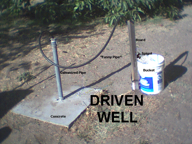
It talks about driving your own 80 foot well with a wooden hammer or a post pounder. And it explains the different type of wells and how to dig them. But I found this homemade hand pump the most interesting.

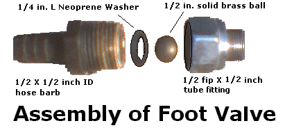
It is made of some hose adapters and a brass ball. It acts as a check valve. This goes down in the well and is attached to some stiff UV resistant irrigation hose. When you pull it up and down it starts pumping water. It may take a lot of effort the first time you set this up but after that it is much quicker because it doesn't lose its prime. I estimate about 50 strokes per gallon.
Also, even if you are going to use an electrical pump, this manual pump still comes in handy for when you first dig the well. It allows you to clear out the sand and silt very quickly.

This type of pump will work for years and doesn't require maintenance. Pretty impressive for just a few bucks at the hardware store. Looks like it would be great for emergencies or for off grid water pumping.

Richard

Wednesday, August 26, 2009

Liar Liar Pants on Fire

Today I was browsing ebay looking at wind turbine stuff. I came across this link here. Here is an excerpt:

Wind Turbine 1000 watt. Complete system minus inverter and battery

This is the Best of the Best. Made in Michigan. Made in the U.S.A.

This high out put 1000 watt Wind Turbine is the best out there to start with;

The frame is made of 6061 aluminum aprox 52 inches long strong yet light. bolted together with stainless steel washers nuts and bolts. This unique designed lets you install the wires down the center of the tube so the wires wont get tangled up.This is truly a work of art.

Dont buy a frame thats made out of cheap steel from china then welded by a amatuer and painted over, the frame will rust crack paint will chip off and will look terrible in weeks

This heavy duty motor/generator can produce a 1000 watts as a wind generator. The wind generator is rated for 130 volts dc 8 amps and reversible (creates electricity spinning in either directions they have thick magnets and brushes inside the housing. The outside housing is painted with white epoxy paint.The motor hits about 12 volts at 12 mph start up speed is about 3-4 mph. This is a awsome motor.

Dont waist your money with one of those 200 watt systems

These blades our the best out there. You get 3 turbo torque aircraft grade aluminum. The blades are about 5 inches wide at their widest and 24 inches in length (diameter of swept area is aprox 52 inches) with hub. These are cnc machined with a dimensional tolerance of .005 inches. They are perfectly balanced and spin very smooth.they are light strong and will not rust built to last , low wind start up about 3-4 mph. Our blades can with stand 70 mph.our blades our field tested and under go hundreds of hours of prototyping.

-------------

This upsets me. Some people read this and don't see the problems.

1) It says a 1,000 watts - and we know that 8 amps multiplied by 130 volts is 1,040 watts. But, in real life we are charging a battery. In this case a 12 volt battery. If the battery is maxed at 15 volts and you put out 8 amps then that is only 120 watts. But in cold strong wind you can get up to 3 times the current rating, making this a 360 watt wind turbine system at best.

2) It only produces 12 volts at about 12 mph wind. But a battery is usually 12.7 volts or more and the voltage drop across the diode is 0.7 volts. That means that you need 13.4 volts or more to start charging. So, with a 4.3 foot diameter blade (52 inches) that means on a breezy day when the average wind speed is about 17 mph, you would only average about 50 watts of power.

3)This is one of those cheap treadmill motor that has very poor bearings. It will break under high winds and prolonged use. These motors don't produce any usable power until you get to high rpms and that means it is a poor choice for wind turbine use.

4) If the blades are 30% efficient and the motor is 50% efficient, then overall the system is 15% efficient. When I put that in my motor analyzer, I get the following:

So, the part of the description that says don't waste your time with a 200 watt system is obviously misleading. This system is basically a 200 watt system in a "real world" situation.

5) Notice that I used a TSR of 5 and RPM of 4500. But, that is very generous of me since most treadmill motors have a 5,000 or more RPM rating. Also, TSR of 5 implies that the blades have lift. A curved surface alone will not make much lift. You need a curved leading edge and a sharp trailing edge. I'm guessing that this blade would have about a 3 to 5 TSR rating.

6) I like aluminum, but remember, even the best aluminum will get micro fractures at stress points and they build up over time. But the thick pvc pipe painted with titanium dioxide paint will last for years.

7) Just because the blades can handle 70 mph winds doesn't mean that the little bearings in that cheap motor can handle that for any length of time.

So, this is about a 200 to 300 watt wind turbine that needs a very breezy location to make any usable power. And the motor bearings will break in about 6 months to a year. There is a way to use these motors and make them last...but this aint it.

Richard

Friday, August 21, 2009

Some more Fog Catchers

I like the concept for collecting water from fog. There are a lot of places that could use this and it requires no electricity.


I have an idea that you could make electricity with this as well, using the "electret effect". But I'll do some more research into that and some testing before I write about that.

Have a good weekend,
Richard

Wednesday, August 19, 2009

Temperature Coefficient for Electrical Resistivity

I remember telling someone in a forum about using stainless steel bolts as a shunt for use as a cheap current measurement. Someone else said that shunts are made with exotic (aka expensive) materials with very low thermal coefficients of resistance. I found this chart not too long ago and thought I would post it.

As you can see, stainless steel has a negligible coefficient. So, I feel vindicated. Stainless steel is exotic by the way. It is just mass produced and used for construction, thus making it pretty cheap.

Richard

Tuesday, August 18, 2009

Video of Motor analyzer update

Here is the video showing it in operation. Remember, if you purchased this in the past then this is a free upgrade.

Monday, August 17, 2009

new version of motor analyzer released

This is the latest version, 1.6, just released. It does VAWT and HAWT now and will save 3 motor configurations. If you have already purchased in the past, I will upgrade you for free. Just send me an email. There is a part that I'll change on the next release. It says, "Power from blades after friction losses" and should now read, "power from blades after all losses".

I'll make a video of the new program in action and post it on youtube and here.

have a good monday,
Richard

Friday, August 14, 2009

Scalable First Flush System for Rainwater Collection


Here is a simple idea for a "first flush" system for rainwater collection. It is made of pvc pipe and the first flush section is made of 4 inch pipe. For every 18.5 inches used, it will hold 1 gallon. It is scalable by adding more pipes to the left side. I could use 2 pipes at 46 inches each and get 5 gallons of first flush capability, for example. The pipes have a bottom cap and a small hole drilled in them. This way, when the rain starts falling, the first 5 gallons would go into these pipes and fill up faster than the small holes at the bottom will drain. When the pipes fill up then all water after that overflows into the storage tank. This rinses away bird droppings, leaves, dust, bugs, etc. If you have a larger roof, you may want more first flush, such as 10 gallons or more.
It also helps to have a way to stop the leaves and big stuff from even getting this far. Some people use screened gutters, or "Rain Tubes", or a screened redirector right before it goes into the first flush section.


You guys have a good weekend.

Richard

Wednesday, August 12, 2009

update solar oven


Got some flat black barbecue paint and painted the solar oven. I will let it dry tonight and then tomorrow put it in the sun to make sure any toxins can gas out. It is high temp paint but I'd like to be safe. Then we can start using it.

Remember, this one doesn't have insulation. When the temp outside is a little cooler, I'll raise efficiency by using the hot box cooker technique. I'll take a bigger box and place a thick blanket over it and push this cooker down into that so that all sides except the top are covered and well insulated.

Most people would build in the insulation but there are issues with that. Whenever the food steams it could get the insulation wet and mess it up. The hot box way means I can take out the insulation super easy after I'm done and let it dry if it gets wet.

Richard

Rooftop Savonious Discussion

I'd like to talk a little about a vertical axis wind turbine positioned on its side. Yeah, I know, it becomes a HAWT when you do that. The main problem is that, in that position, it doesn't spin from all wind. But there are some advantages. Firstly, it is low profile and neighbors are less likely to complain. Secondly, it is technically easier to mount this way. Standing straight up means the mount point has to be way stronger due to massive torque effects. And thirdly, you can link several wind turbines in a row to share shaft power to one powerful generator.

There is also an advantage to putting a VAWT on the rooftop. When the wind comes, it is compressed upward and effectively gives the savonious more surface area of wind collection. If the wind is traveling perpindicular to the axis then you will get your maximum power potential. In the below example, there is a VAWT 8 feet long and 4 feet wide and it s laying down on its side at the rooftop. In this example the roof rises 8 feet. That means that whatever power the wind turbine would generate in a given wind is multiplied by 3. Of course, a different roof and sized wind turbine would generate different results. So, if it ran at 15 % efficiency normally, then on the rooftop it could be up to 45% efficient. Also note that wind at the peak of the house is stronger than wind at the ground level.

In the below picture you will see wind angles at 45 degrees from perpindicular to the axis. At 45 degrees, the wind turbine should appear to have half the surface area. So, half of 45% would be 22.5% efficiency, still good. At some angle greater than 45 degrees the silouhette would become one third of full and, due to the roof, would make the overall efficiency become 15%. In other words, you can get normal power even at extreme angles. An at perpindicular angles, get 3 times the normal power output.

Some roofs have sections that are perpindicular to each other. Another VAWT could be mounted there as well. That way you generate power no matter what direction the wind comes from. And even if you only have one, whenever the wind direction changes back to a better angle, the power increase more than makes up for the times when no power was generated. Just make sure that your predominant wind is the right direction, otherwise this just wouldn't work for you.

Richard

Tuesday, August 11, 2009

DC Motor Analyzer Finished

Well, it looks like I've finished the updates on my DC motor analyzer software. I still have to do some more testing before I make it available but here are some screenshots. The yellow highlighted sections are new parts to the program. They are only highlighted here for you to see, the program normally doesn't show that. The first picture below is in the HAWT mode, or horizontal axis wind turbine. The second picture is in VAWT mode. So, you can do savonious or other vertical axis wind turbines.


Something to be aware of if you go to the VAWT calculator web page on my website, is that those computations also account for about a 55% efficiency dc motor. So, if you take a savonious and the blades are 15% efficient and the motor is 55%, then on the new motor analyzer software you would put in 8% efficiency. On the website, this was done in the background. But the new program gives you more control.

For instance, if you have blades that are 30% efficient for a HAWT and your DC motor is 60% efficient, then you can put 18% in the efficiency field and get a nice "real world" expectation. Especially when you put in the cable length and gauge.

I should have my testing done by this weekend at the latest and the new analyzer should be available for purchase.

Richard

Monday, August 10, 2009

Cardboard Solar Oven

This is the third solar oven that I've made over the last few years. But this is the first cardboard one I've made. This first pic is the oven without the lid and the second picture is with the lid on.


I still have to paint the inside with some flat black paint. I'll leave the top back 1/4 or so unpainted.

My first test will be without any insulation, just like you see in the pictures. Then I will try the hot box cooker approach. I will take a bigger box and a thick blanket or two and push this down inside so it will be surrounded by the blankets except the glazing section. Then I will add a reflector and see if it improves. Although a reflector mounted on the back of a slant face oven is almost pointless unless the sun is really high, or unless you have a flat top glazing.
And something to be aware of is that (as is true for all solar) size is king, or in this case, surface area of the glazing is king. Here is a picture of a small solar oven that has a 1 square foot piece of glazing letting the sun in.
With the reflector put into position and if it is facing the sun perfectly it will have 3.5 square feet of solar collection. You could make a solar oven with a slanted face that has 3.5 square feet of glazing and you would get the same efficiency without the reflectors.

Also, be aware that reflectors can get in the way. If you don't rotate that funnel type every 30 minutes to an hour, then you will get shadows from the reflectors.

Earlier testing with a thin plywood solar oven with no insulation showed temperatures from 190F up to 225F on a sunny summer day. I expect about the same with the cardboard one.
I'll keep you guys posted.

Richard

Friday, August 7, 2009

Rocket Stove

I was talking about hot box cookers the other day and thought this would be an appropriate method for bringing food to a boil and then using the hot box to finish it off. This one is really simple and made with just some adobe bricks.

I like the rocket stoves because they make a lot of heat with very little input. They fact that they are smokeless tells me that they are very efficient. And combined with the hot box method, this is an off the grid dream come true.

See ya Monday,
Richard